Just a small project early this morning. Throwing together things that have been sitting around colleting dust the last few years. I got this foot pedal from the thrift store years ago for cheap, although I don't remember how much it was. It couldn't have been over $10 though, or I wouldn't have bought it.

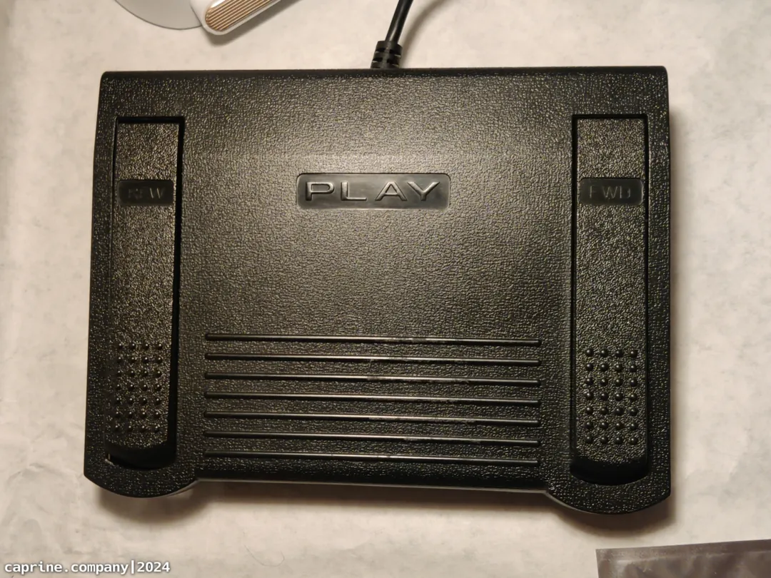
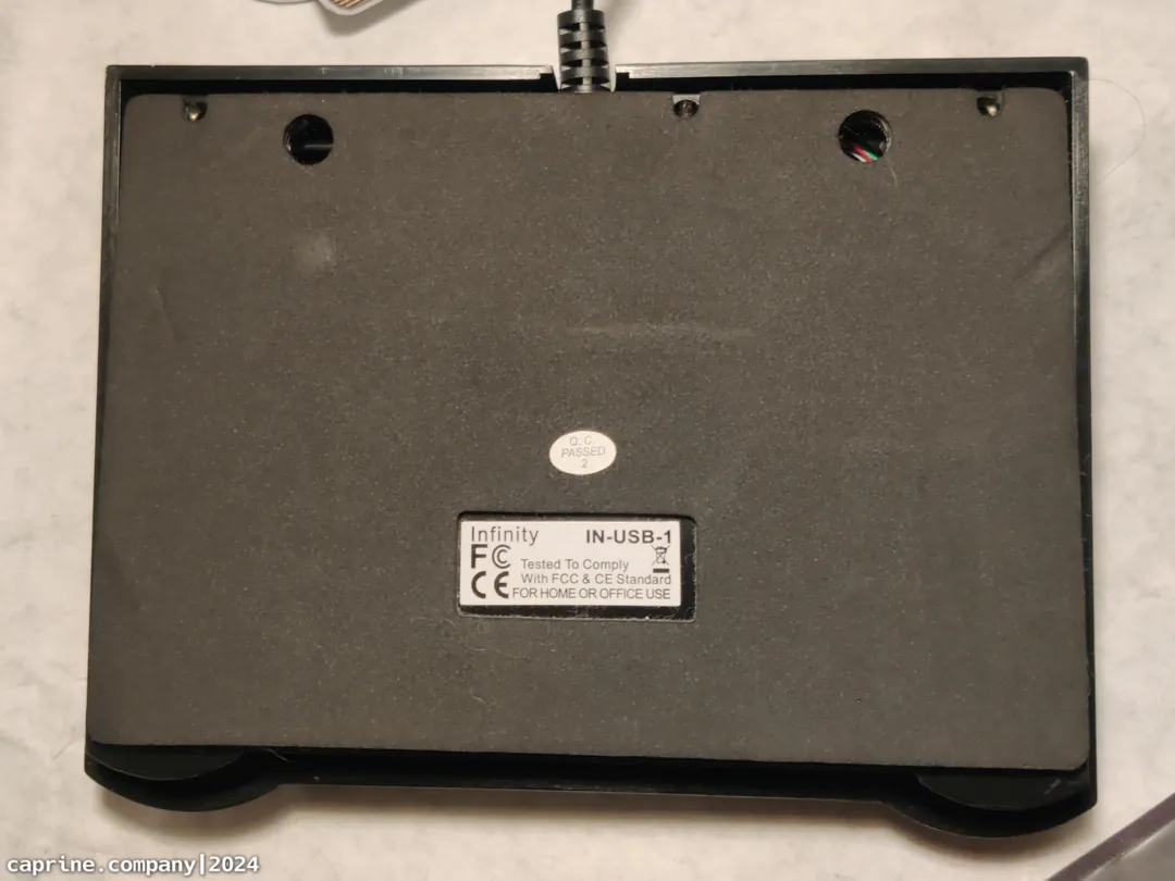
One of my goals for a long time was to integrate a foot pedal system into my setup somehow. This one fits the bill (not perfectly), although it turns out that it needs some kind of special driver that I didn't have. No normal keyboard keycodes are sent to the computer, so it's definitely not recognized as a keyboard. Checking it with lsusb on Linux gives this result:
lsusb verbose output
Tech Tangents on YouTube has a video about writing a little driver in Linux to make it work. This is a cool solution if you're already using Linux and want to save some money. I wanted this to be platform agnostic though, which is why I did a controller swap.
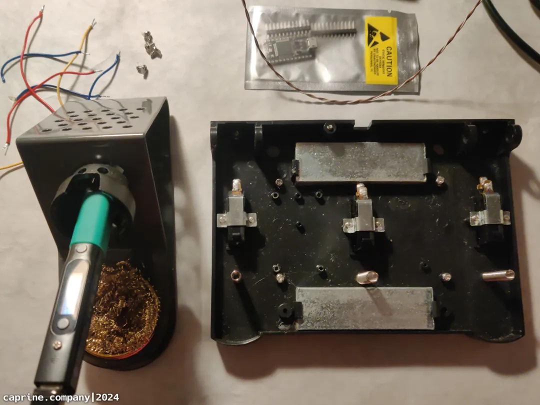
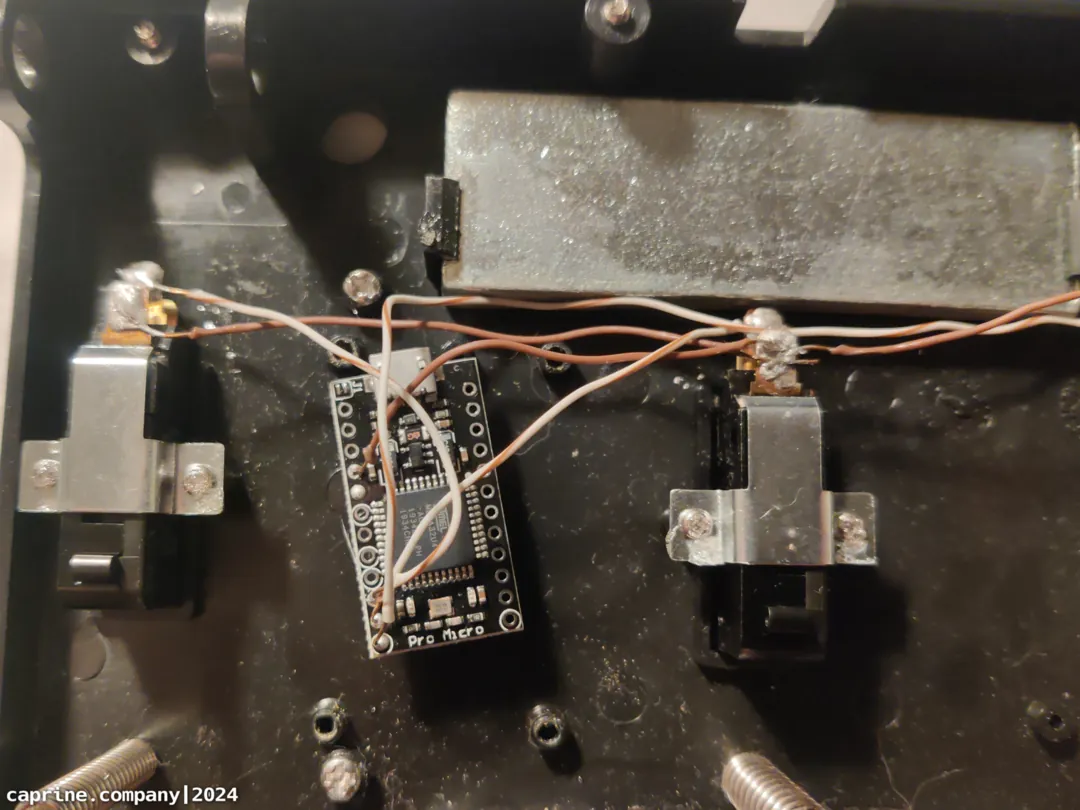
After that initial testing all that time ago I ended up kinda forgetting about it I guess. Fast forward to now and I thought about it again. Thought to myself that it could be useful to have a foot switch for an action in Blender or a game or anything really. I had an Arduino Pro Micro sitting around, which is all you need to get this working as a QMK programmable foot switch. QMK also includes a set of "Easy Maker" firmware presets, which makes it super easy for someone who just wants to get a simple one-off project up and running. You could use a handful of other MCUs with the ez_maker presets too.
Process
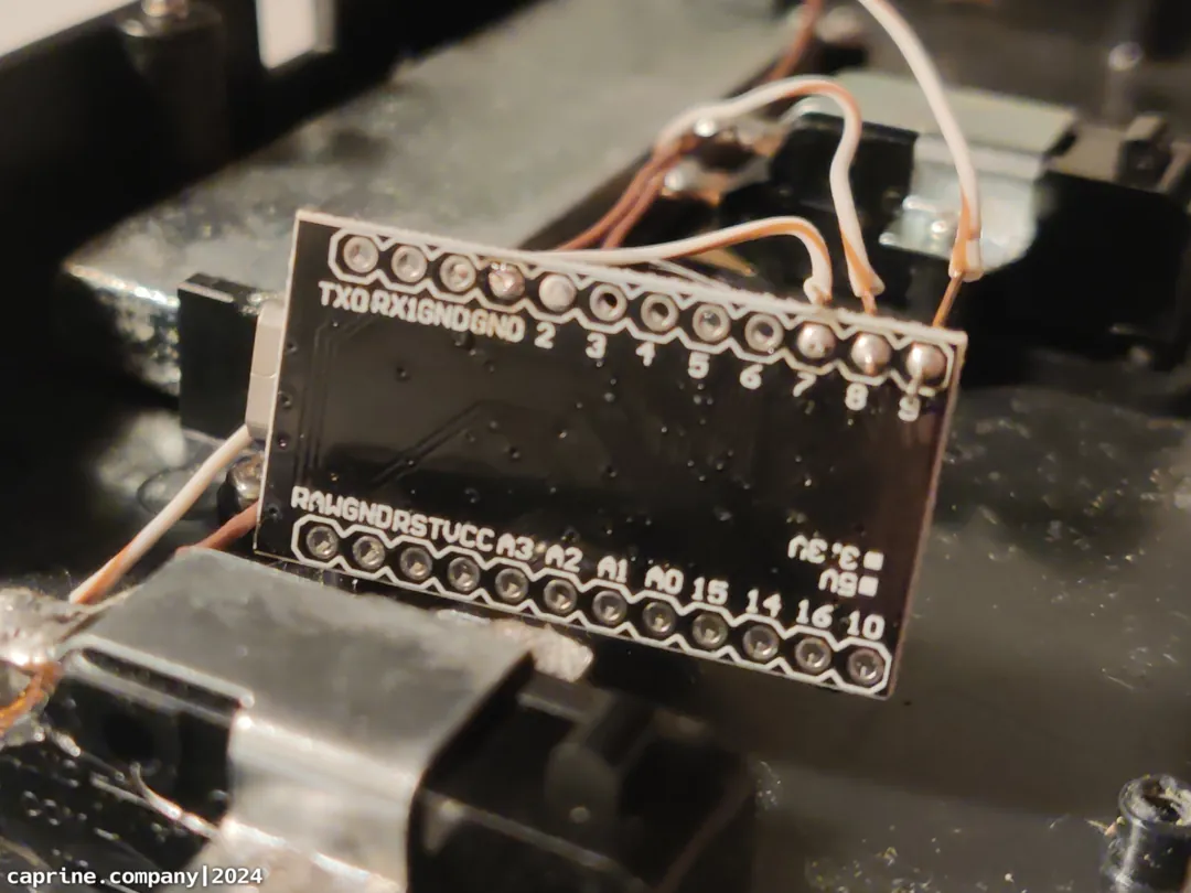
All you gotta do to convert a foot pedal like this is to open it up and solder a few wires. I took a bunch of pictures to show the process.
Also don't forget to add a reset switch somewhere that's easily accessible on the outside. I forgot and now need to take the thing apart and solder in a switch.
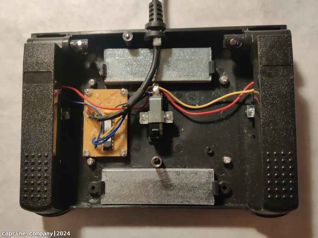
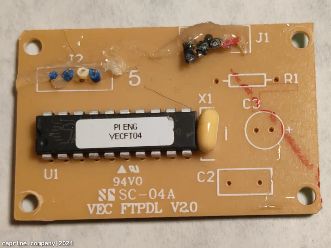
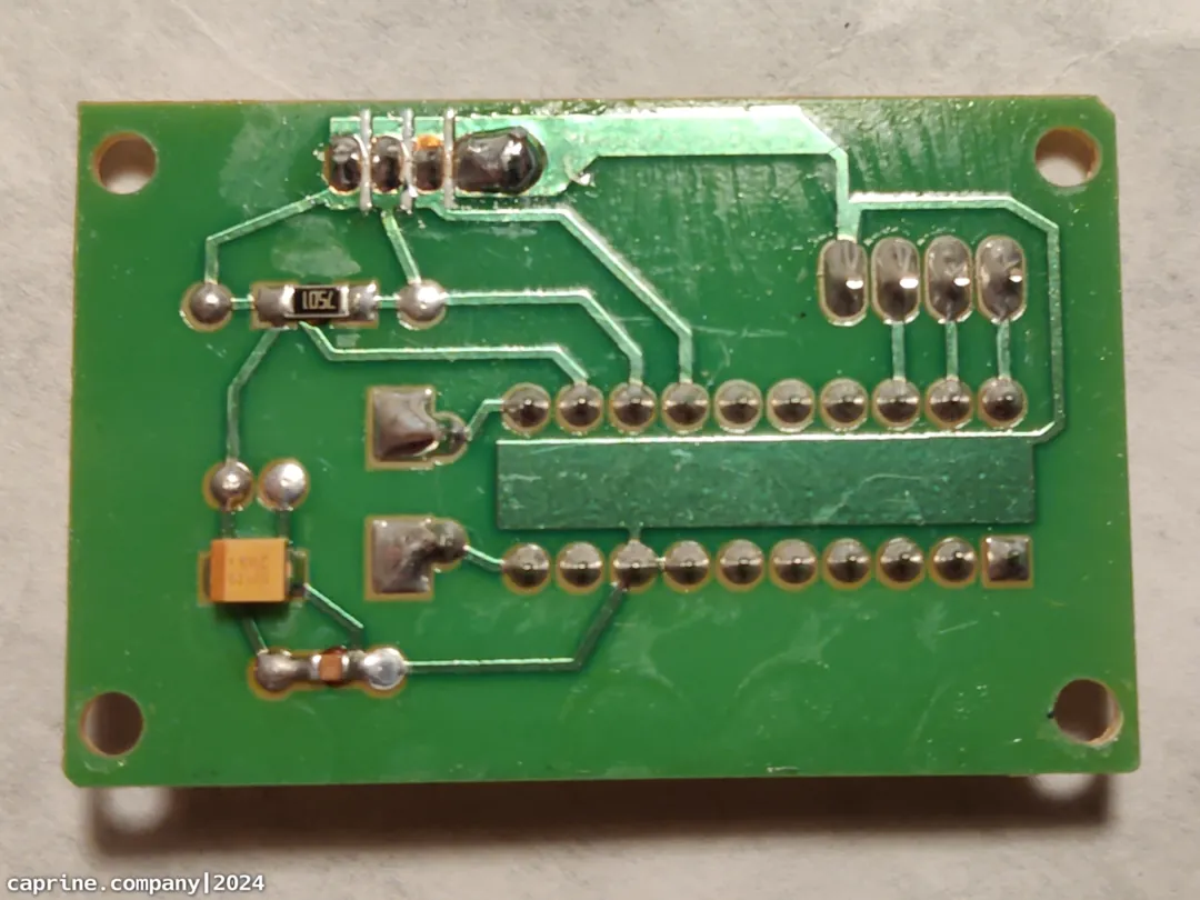
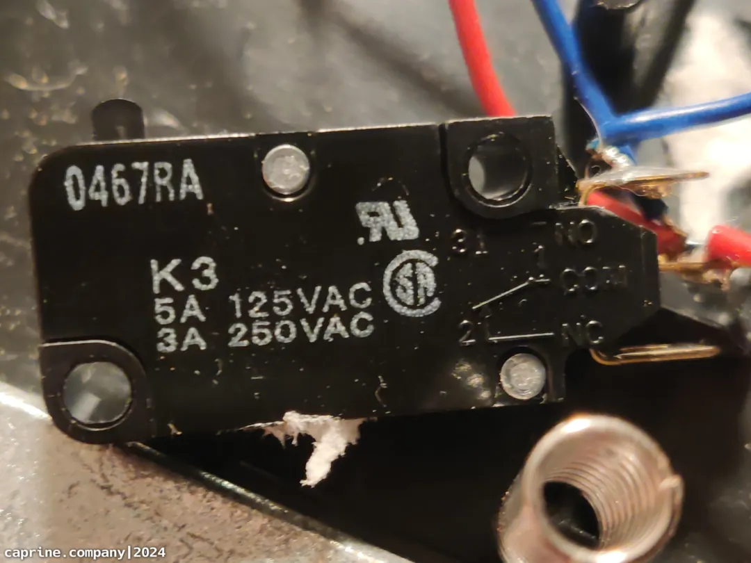
After chopping out the PCB from the original wiring, I decided that I wanted to redo the way the switches were wired up. This probably wasn't necessary, but it never hurts to get some practice doing soldering anyways. I just hooked one pin from all the switches up to a common ground, and then wired another pin to whatever available pins were on the MCU. In this case I used pins 7, 8 and 9.
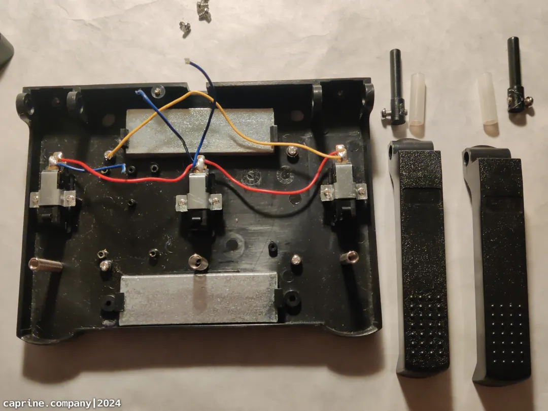
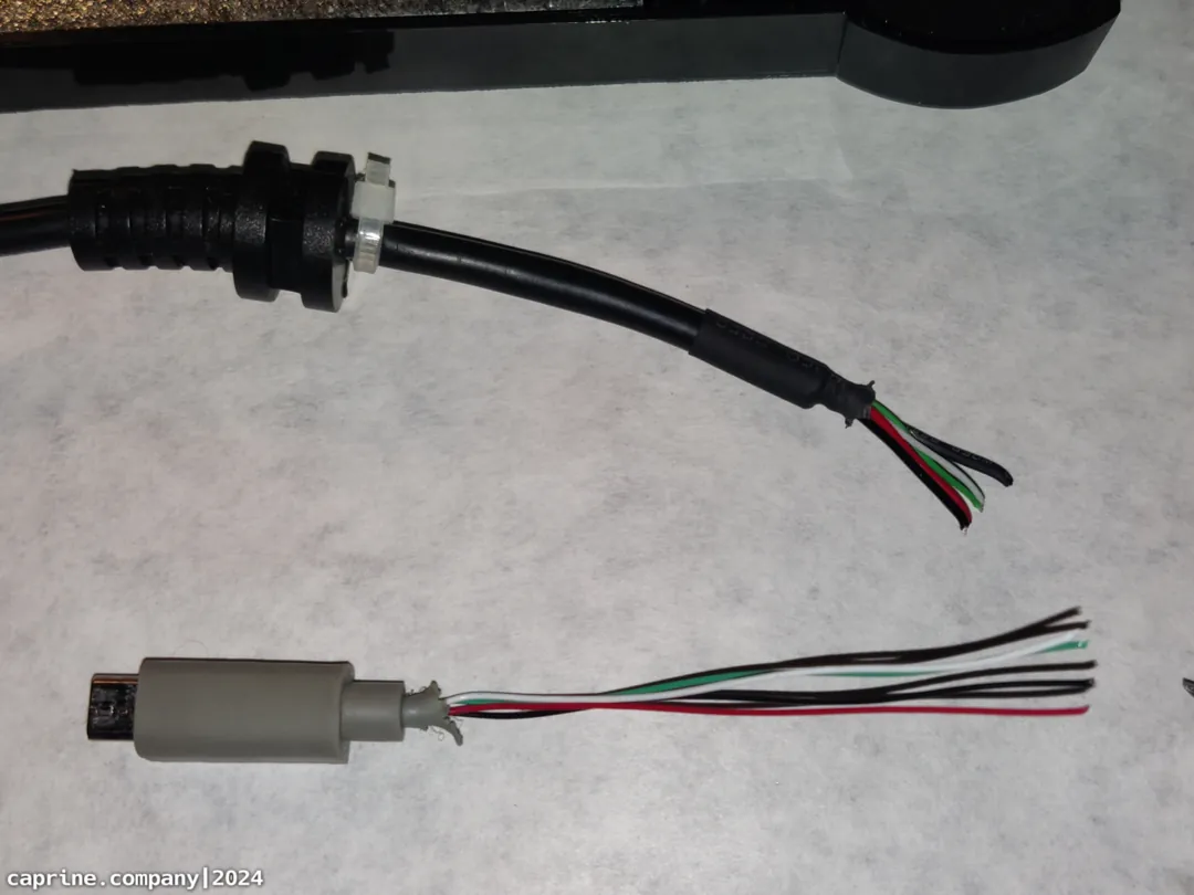
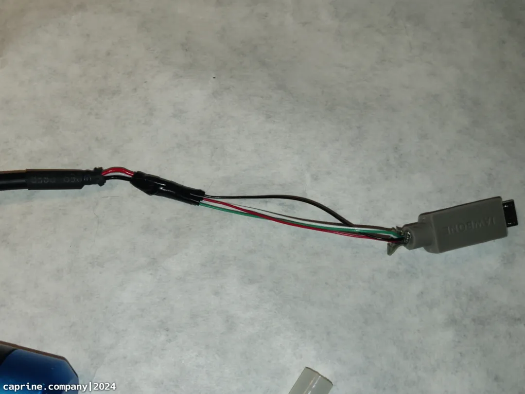
I wanted to retain the original long durable USB cable, so I hacked off the end of a Micro USB cable that was falling apart and soldered them together. Then everything goes back in the case and gets hot glued down.
Firmware
The firmware is dead simple thanks to that ez_maker template in QMK Configurator. By default it outputs C, E and G. You can change this to any keycode or macro with the web tool. I would eventually like to get this working properly with Vial, but that would take some learning on how to port or build a custom layout for it. If I end up doing that I'll link it somewhere in this section. I have no plans for what to map the buttons to yet, but I was playing some TBoI earlier and found it was fun to place down bombs with my foot pressing the big center button.
A thought I had regarding use cases would be to make the left and right buttons change the layer you're on, and the big center button being the primary action. So you could switch between Blender mode or game mode and so on.
End
That's about it with this project. This was another push for myself to get a post out within 1 day. Not that I'm on a schedule or time limit or doing this for money. I just want to refine the workflow and make things smooth for posting to this site. I wrote some more shortcodes for this post to make embedding codeblocks and side-by-side images possible. The worst part of the website workflow so far is the image processing. It takes a long time and some tedious work to get the watermark in place and to scale the image to the right size to save on bandwidth. Ideally I'd make some kind of little script tool that can batch process a selection of images I provide it. Maybe at some point I'll figure that out.
Thanks for reading.